
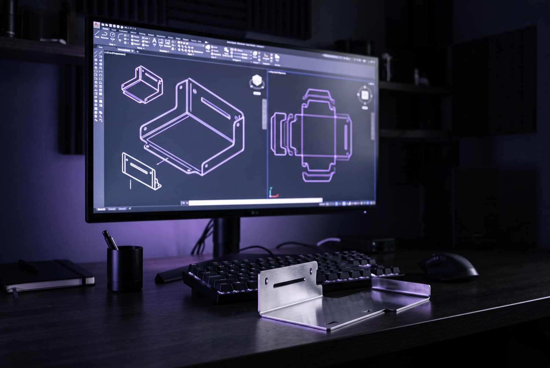
CAD formats are the language in which designs and drawings travel between you and your manufacturing partner. In sheet metal fabrication, five formats have become standard: DXF and DWG for two-dimensional contours, and STEP, IGES and STL for three-dimensional models. Laserteile Online's online calculator processes all five directly – up to 516 MB per file, as a ZIP or batch upload if you like, with an instant price and no registration.
Why the CAD format decides speed and price
Understanding the different CAD formats and how they're used is essential for smooth workflows and cost-efficient processing. A well-prepared CAD file doesn't just make importing into the processing software easier – it can also affect the quoted price: the more usable the file, the simpler and cheaper the processing. The reverse is true too: messy data costs time – every query, every manual rework delays the start of production.
The three categories of CAD data
2D CAD formats: DXF and DWG
These include file formats such as DXF (Drawing Exchange Format) and DWG (AutoCAD Drawing). They're used for two-dimensional drawings and are widely used in sheet metal fabrication. For flat laser-cut parts with no bends, the 2D contour is the most direct description of the component – it contains exactly what the laser will cut. You can read more about the cutting process itself on the laser cutting page.
3D CAD formats: STEP, IGES and STL
3D CAD formats include STEP (Standard for the Exchange of Product Data) and IGES (Initial Graphics Exchange Specification). They allow three-dimensional models to be created and displayed, and are especially useful for complex parts – for example bent parts, where the 3D model directly represents the bends and the sheet thickness. STL describes the part's surface as a triangulated mesh and originally comes from the world of visualisation and display models.
Images and drawings
Although not CAD formats in the strict sense, images or scanned drawings can serve as a starting point in some cases. Bear in mind, though, that converting such files into usable CAD data takes time and accuracy suffers – they're not suitable for an instant price in the calculator.
Format overview: which format for what?
| Format | 2D / 3D | Suited for | What the calculator reads from it |
|---|---|---|---|
| DXF | 2D | Flat laser-cut parts with no bends, series production | Cut contours: cut length, material requirement, instant price |
| DWG | 2D | Drawings from the AutoCAD environment | Same as DXF: contours and dimensions |
| STEP | 3D | Bent parts, complex components, assemblies | Solid model including bends and sheet thickness |
| IGES | 3D | Data exchange between different 3D CAD systems | Surface and solid geometry of the part |
| STL | 3D (mesh) | Display models, visualisation | Triangulated mesh of the part shape |
Laserteile Online's calculator accepts all five formats directly – individually, as a batch, or bundled in a ZIP archive, up to 516 MB per file.
Which formats are used most often?
Both 2D and 3D CAD formats are widely used in metal fabrication. The choice depends on the complexity of the project and the specific requirements: 2D formats such as DXF are often more efficient for series production of simple laser-cut parts, because they provide the cut contour directly, with no detours. 3D formats such as STEP are preferred for more complex parts and demanding applications, because they represent geometries and bends directly – the flat pattern of the sheet can be derived from them without a separate drawing.
Practical tips for clean DXF exports
Most queries in sheet metal fabrication can be avoided with a few simple steps at export:
- Export at a 1:1 scale in millimetres – scaled drawings lead to incorrectly sized parts.
- Use closed contours: open or self-intersecting polylines can't be interpreted unambiguously by the cutting software.
- Leave only the cut geometry in the file – remove dimensions, hatching, drawing frames and text fields before export, or move them to hidden layers.
- Clean up duplicate lines: overlapping elements are otherwise cut twice, or distort the cut-length calculation.
- Convert splines to polylines or arcs where possible – this improves compatibility between CAD systems.
- One part per file: for multiple parts, simply upload a ZIP or batch upload in the calculator.
A detailed step-by-step guide is available in the Creating a DXF file guide.
Dealing with unusable data
If CAD data can't be processed in its current form, we'll get in touch. As a rule, metal fabrication companies can handle almost any file format – what matters is clear communication about the necessary adjustments. In such cases, Laserteile Online contacts you with a specific note on what needs to be adjusted in the file so the job can start without delay.
A special case: CAD data can be generated from clear black-and-white images if no CAD files are available – for example for logos or ornamental designs. Bear in mind, though, that the accuracy of such vectorised data can be lower than that of originally constructed CAD files.
Conclusion
Choosing the right CAD format is essential for a smooth, cost-efficient manufacturing process: DXF and DWG for flat laser-cut parts, STEP and IGES for bent parts and complex geometries. If you pay attention to closed contours, a 1:1 scale and clean layers when exporting, Laserteile Online's online calculator gives you a binding instant price in seconds – with no registration required.